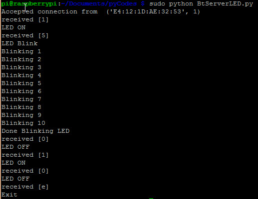
NodeMCU control Web Animation through Cloud MQTT
ควบคุม เว็บแอนิเมชั่น ด้วย NodeMCU ผ่านคลาวด์เซอร์วิซ CloudMQTT
สวัสดีครับหลังจากที่ผมได้ลองทดลองทำคลิปโพสบน Youtube ไปซักพักก็มีเพื่อนถามมาว่าทำอย่างไร นิ่งไปนานเพราะจำไม่ได้ว่าทำอะไรลงไปบ้าง ฮา…. วันนี้มีเวลาเลยค้นไฟล์รวบรวมมาเขียนสรุปอีกครั้งครับ (ก่อนจะลืมแบบถาวร T^T)
Scenario สถานการณ์
สถานการณ์นี้เราอยากจะสั่งงานโดยการกดปุ่ม สวิตช์ หรือรับค่ามาจากเซนเซอร์จับการเคลื่อนไหว ที่ต่อด้วยกับ NodeMCU หรือใช้ ESP8266 ก็ได้ เมื่อกดปุ่มแล้ว เราจะส่งข้อความไปที่ Cloud Broker ซึ่งอีกฝั่งเป็น Web app animation ที่เราสร้างขึ้นมาให้เชื่อมต่อ (subscribes) กับ Cloud Broker ไว้คอยเช็คว่ามีข้อความเข้ามาหรือไม่ ถ้ามีข้อความเข้ามา(สวิตช์ถูกกด) แอนิเมชั่นของเราจะทำการเล่น

อุปกรณ์ฮาร์ดแวร์ Hardware
- NodeMCU หรือ ESP8266
ซอฟต์แวร์ Software
- Arduino IDE
- CloudMQTT
- Adobe Edge Animate CC
ขั้นการสมัครใช้ฟรี Cloud Service (CloudMQTT)
- เริ่มเข้าไปสมัครกันเลยครับที่เว็บ https://www.cloudmqtt.com/

2. หลังจากสมัครเสร็จเรียบร้อยแล้ว ให้เข้าไปที่ Control Panel

3. ที่ CloudMQTT Console ให้สังเกตุที่หน้า Overview จะมีข้อมูลที่ต้องจดจำคือ Server, User, Password และ Port

ขั้นตอนการเขียนโปรแกรมสำหรับ NodeMCU หรือ ESP8266
- เขียนโปรแกรมตามตัวอย่างเลยครับ หรือ สามารถโหลดได้ที่ https://github.com/spidyhero/NodeMCU_MQTT/blob/master/MQTT_HelloMama_example.ino

/*
 MQTT publish/subscriber example https://www.cloudmqtt.com/

  - connects to an MQTT server
  - publishes to the topic "outTopic"
  - subscribes to the topic "outTopic"

  Modified by SpidyHero
*/

#include <ESP8266WiFi.h>
#include <PubSubClient.h>

// constants won't change. They're used here to
// set pin numbers:
const int buttonPin = 0;     // NodeMCU pushbutton pin
const int ledPin =  16;      // LED pin on NodeMCU

// variables will change:
int buttonState = 0;         // variable for reading the pushbutton status

//-------------------------------//

const char *ssid =  "xxxxx";   // your WiFi network name
const char *pass =  "xxxxx";   //your WiFi network password

// Update these with values suitable for your network.
IPAddress server(xx,xx,xxx,xxx); // CloudMQTT Server IP, ping m11.cloudmqtt.com to get IP

WiFiClient wclient;
PubSubClient client(wclient,"m11.cloudmqtt.com", 18940); //your MQTT Port number

// use this function to receive message from CloundMQTT subscribes topic
void callback(const MQTT::Publish& pub) {
  Serial.print(pub.topic());
  Serial.print(" => ");
  Serial.println(pub.payload_string());
}

// setup
void setup()
{
  // Setup console
  Serial.begin(115200);
  delay(10);
  Serial.println();
  Serial.println();

  // initialize the LED pin as an output:
  pinMode(ledPin, OUTPUT);
  // initialize the pushbutton pin as an input:
  pinMode(buttonPin, INPUT);

  client.set_callback(callback);

  WiFi.begin(ssid, pass);

  int retries = 0;
  while ((WiFi.status() != WL_CONNECTED) && (retries < 10)) {
    retries++;
    delay(500);
    Serial.print(".");
  }
  if (WiFi.status() == WL_CONNECTED) {
    Serial.println("");
    Serial.println("WiFi connected");
  }

//----MQTT validate connection ----//

  if (client.connect(MQTT::Connect("NodeMCU")
                    .set_auth("CloudMQTTusername", "CloudMQTTpassword"))) {
    Serial.println();
    Serial.println("Publish success.");
    client.publish("outTopic","NodeMCUconnected"); //Publish/send message to clound on outTopic

    Serial.println("Subscribe success.");
    client.subscribe("outTopic"); //Subscribes topic to receive message from cloud and print on monitor

               }
}

void loop()
{
  client.loop();

  // read the state of the pushbutton value:
  buttonState = digitalRead(buttonPin);

  // check if the pushbutton is pressed.
  // if it is, the buttonState is HIGH:
  if (buttonState == HIGH) {
    // turn LED on:
    digitalWrite(ledPin, HIGH);
  }
  else {
    // turn LED off:
    // send message to your topic when release button
    digitalWrite(ledPin, LOW);
    client.publish("outTopic","button is pushed"); // send message to "outTopic" when release button
    Serial.print("button is pushed");
    Serial.println();
    delay(300);
  }

}
บรรทัดที่ 24 ให้ระบุชื่อ WiFi ที่เราจะทำการเชื่อมต่อ
บรรทัดที่ 25 ให้ระบุ Password ของ WiFi ที่เราจะทำการเชื่อมต่อ
บรรทัดที่ 28 ให้ระบุ IP Server CloudMQTT เลขนี้ได้มาด้วยการ ping m11.cloudmqtt.com ใน Console

บรรทัด 72 ให้ระบุ CloudMQTT username และ password
เสร็จแล้วเราก็ลองอัพโหลดเข้าNodeMCU หรือ ESP8266 กันเลยครับ….
ขั้นตอนการสร้าง Web Animation

เริ่มต้นเรามาสร้างไฟล์งานใน Adobe Edge กันเลยครับ ในที่นี้ผมจะยกตัวอย่างไม่ซับซ้อนก่อนครับ
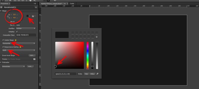
- ขั้นแรกให้เราสร้าง stage กำหนดขนาด และสี ของพื้นที่แสดงผลก่อน
2. สร้างพื้นที่แสดงข้อความที่เรารับมาจาก CloudMQTT
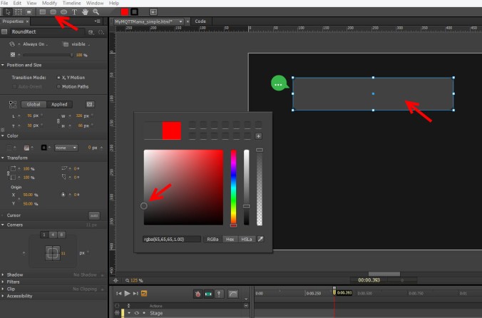
3. สร้าง Text ข้อความเพื่อแสดงข้อความ ตั้งชื่อว่า message

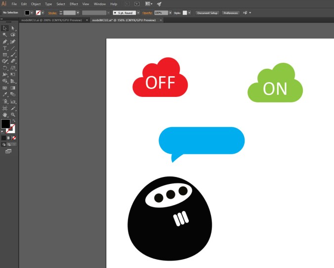
4. สร้าง icon แสดงสถานะการเชื่อมต่อกับ CloudMQTT เมื่อเชื่อมต่อได้แสดงไอคอนสีเขียว ถ้าเชื่อมต่อไม่ได้ให้แสดงสีแดง และสร้างวัตถุอื่นๆไว้รอได้เลยครับ ผมใช้ Adobe Illustrator CC ในการสร้างVectorต่างๆไว้
5. เราสามารถ Copy จาก AI และ Paste ลงใน AE ได้ดดยตรงเลย ไฟล์ที่นำเข้ามาจะเป็น SVG

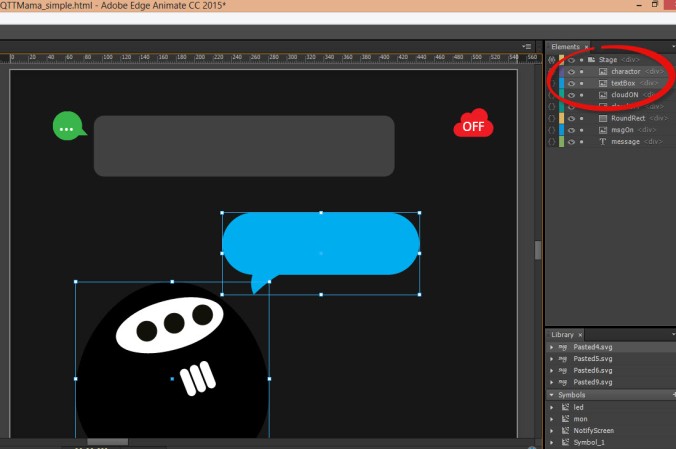
6. ตั้งชื่อให้กับ Vector ที่เรานำเข้ามา โดยตอนนี้เราจะมี ไฟล์ cloudON สีเขียว และ cloudOFF ที่เป็นสีแดง
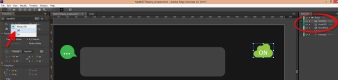
7. จัดตำแหน่งไว้ โดยเราจะนำมาซ้อนกันดังรูป เราสามารถกดเครื่องหมายรูปดวงตาเพื่อแสดง/ซ่อนการแสดงผล


8. กดรูปตาเปิดการแสดงผลให้กับ CloudON (สีเขียว) แลัวให้เราตั้งStyleการแสดงผลด้านซ้ายมือ จาก Always On เป็น Off เพราะเราจะเขียนScript ให้เปลี่ยนเป็น On เพื่อแสดงการเชื่อมต่อภายหลัง ตอนนี้จะเห็นสีแดงแสดงผลอย่างเดียว
9. นำตัวละคร และ กล่องข้อความที่สร้างไว้ใน AI เข้ามาและตั้งชื่อว่า character และ textBox
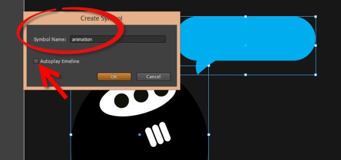
10.ตั้งชื่อSymbol ว่า animation และยกเลิกการเล่นอัตโนมัติ
11. เราสามารถแก้ไข Symbol ได้โดยดับเบิ้ลคลิ๊กที่ไอคอนSymbol ชื่อ Animation

12. สร้างตัวอักษรตามต้องการดังภาพ

13.ทำการ Group text และ textBox เข้าด้วยกันโดย Shift select คลิ๊กขวาและเลือกGroup (Ctrl+g)

14.เปลี่ยนชื่อเป็น messageBox

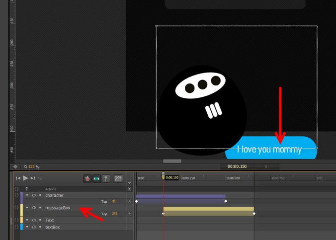
15. เราจะมาทำการแอนิเมท Character ก่อน โดยเลือกที่character และกด Pin ไอคอนแล้วลากเพื่อกำหนดเวลาในการเคลื่อนที่บนTimeline

16. ใช้เมาส์คลิ๊กลากcharacter ลงมาด้านล่างให้พ้นกรอบของ Symbol

17.กำหนดรูปแบบของแอนิเมชั่น Easing แบบ Ease Out >Back ดังภาพ

18. ทดสอบแอนิเมชั่นโดยการกดปุ่ม Enter หรือลาก Play head ที่ Timeline ดู จะเห็นว่าตัว character เราจะเด้งขึ้นมาเมื่อเล่นแอนิเมชั่น
19. ชุดตัวอักษร messageBox ให้ทำเช่นเดียวกันแต่อาจกำหนดเวลาให้ช้ากว่าเล็กน้อย ดูTimelineในภาพด้านล่าง เมื่อทดลองเล่นแอนิเมชั่นแล้ว จะเห็นว่าตัว character จะเด้งขึ้นมาก่อนและตัวอักษรจะเด้งขึ้นตามมา

https://www.cloudmqtt.com/docs-websocket.html
…..เดี๋ยวกลับมาเขียนต่อครับ…..to be continuous…
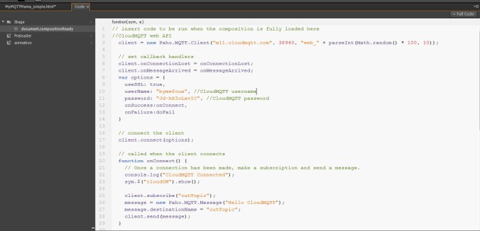
โค้ดทั้งหมดของ Adobe Edge Animate
//CloudMQTT WebSockets
  client = new Paho.MQTT.Client("m11.cloudmqtt.com", 38940, "web_" + parseInt(Math.random() * 100, 10));

  // set callback handlers
  client.onConnectionLost = onConnectionLost;
  client.onMessageArrived = onMessageArrived;
  var options = {
    useSSL: true,
    userName: "xxxxxxx", //CloudMQTT username
    password: "xxxxxxx", //CloudMQTT password
    onSuccess:onConnect,
    onFailure:doFail
  }

  // connect the client
  client.connect(options);

  // called when the client connects
  function onConnect() {
    // Once a connection has been made, make a subscription and send a message.
    console.log("CloudMQTT Connected");
	 sym.$("cloudON").show();

    client.subscribe("outTopic");
    message = new Paho.MQTT.Message("Hello CloudMQTT");
    message.destinationName = "outTopic";
    client.send(message);
  }

  function doFail(e){
    console.log(e);
  }

  // called when the client loses its connection
  function onConnectionLost(responseObject) {
    if (responseObject.errorCode !== 0) {
      console.log("onConnectionLost:"+responseObject.errorMessage);
    }
  }

  // called when a message arrives
function onMessageArrived(message) {

   //get date time
   var d = new Date();

   console.log("Message from cloud: "+message.payloadString);

	sym.$("message").html("Cloud Message: "+message.payloadString+"
"+"Time: "+d);

	setTimeout(function() {sym.getSymbol("animation").stop(0);},2500);
   sym.getSymbol("animation").play(0);

  }
…..เดี๋ยวกลับมาเขียนต่อครับ…..to be continuous…